

Subscript
1. Introduction
2. Results and discussion
3. Conclusions
Supplementary
Materials and Synthesis
Device Fabrication
Solar Cell Characterizations
References
Subscript
LS : light soaking
PSCs : polymer solar cells
ETL : electron transport layer
ZnO : zinc oxide
PCE : power conversion efficiency
O2 : oxygen
H2O : moisture
-COOH : ester
-OH : alcohol
Tg : glass transition temperature
SMs : surface modifiers
CPEs : conjugated polyelectrolytes
PEI, PEIE : polyethyleneimines
SAMs : self-assembled monolayers
ILs : ionic liquids
TiO2 : titanium oxide
D-π-A : π-conjugated donor-acceptor
SGT-021 : porphyrin-based dye
BDT : benzothiadiazole
HC-A1 : co-adsorbent
DSSCs : dye-sensitized solar cells
ITO : indium tin oxide
NPs : nanoparticles
MoO3 : molybdenium oxide
Ag : silver
RT : room temperature
PNTz4T : poly(2-decyltetradecyl)thiophen-2-yl)naphtho[1,2-c:5,6-c′]bis[1,2,5]thiadiazole, 5,5′-bis-(2,2′-bithiophen-2-yl)
MTC : methyl thiophene-3-carboxylate
ffBT : difluorobenzothiadiazole
T3 : terthiophene
THF : tetrahydrofuran
VOC : open-circuit voltage
JSC : short-circuit current density
FF : fill factor
EQEs : external quantum efficiencies
µe : electron mobility
Jph : photo-current density
PC : charge collection probability
RH : relative humidity
RSH : shunt resistance
1. Introduction
Polymer solar cells (PSCs) based on fullerene acceptors have gone through extensive research over the last couple of decades to improve power conversion efficiency (PCE) from merely 1% to over 11% in single junction binary component based solar cells1-10). These benchmark fullerene-based PSCs are widely used for the in-depth studies of charge carrier dynamics and the efforts are being put into to design efficient and stable PSCs. To further push this class of plastic electronics into the marketable product, one has to design PSCs which are stable under outdoor operational conditions which includes one sun light source, heat and humidity. On contrary to the PCE in these PSCs, the light soaking (LS) stability remains a hitch to their further outgrowth11-14). Although with proper encapsulation of the PSCs, the effect of the environmental factors such as oxygen (O2) and moisture (H2O) can be mitigated15-17). Yet, these PSCs suffer instability issues when tested for LS stability, and the instability in these fullerene-based PSCs arises from multiple reasons including: 1) photoactive materials itself, 2) blend morphologies of the photoactive layer, 3) charge transport layers, and at last but not least, the 4) the interface between the transport layers and the photoactive layer13,18-24). Unless, these issues are properly addressed, the future of this class of PSCs remains a challenge to attain. Provided that an optimized blend morphology is achieved in a given photoactive system, the critical parameter left behind is to fabricate PSCs with stable electrodes and having stable electrode-photoactive layer interface.
Among different methods affecting the stabilities in fullerene based PSCs as described above, modification of the polymer or small molecule to synthesize fullerene-compatible electron donor is most commonly employed to achieve stable blend nano-morphologies. For instance, electron donor polymer with side-chain functionalization containing ester (-COOH) or alcohol (-OH) group is an effective approach to design stable polymers where high thermal stability in these PSCs is attributed to the high Tg’s of the ester or alcohol modified polymers which restricts the severe phase separation and crystallization18). Moreover, the higher compatibility of the ester-modified polymers with fullerenes is also proven to enhance the thermal stability in these type of PSCs due to improved interfacial contact of ester-modified polymer and fullerenes25). One of the reason for the low LS stability is the aggregation of the fullerenes under light and heat, where the accumulation of high electrostatic potential energy of fullerenes after absorption of UV-photons leads to the destruction of the optimal nanomorphology26). The use of the UV-cut filters to filter out these high energy photons to avoid the excessive aggregation of fullerenes is an alternate approach to enhance LS stability26,27). Other methods to improve stabilities in fullerene based PSCs includes finding compatible charge transport layers and the optimizations of the interface between these layers and the photoactive films, which play vital role towards not only the enhancement of PCE but also the stability20,28-30). Optimizations of the electron transport layers (ETLs), particularly zinc oxide (ZnO), is of great importance due to well-matched energy levels with photoactive layers.
ZnO is a robust, solution processable ETL having high transparency, high carrier mobilities, low cost and appropriate energy levels with respect to the photoactive layers in PSCs31,32). The modification of ZnO is an active area of research for the simultaneous enhancement of PCE and stability in PSCs. Surface treatment of ZnO with varied surface modifiers (SMs) including conjugated polyelectrolytes (CPEs), polyethyleneimines (PEI and PEIE), self-assembled monolayers (SAMs), ionic liquids (ILs), organic dyes etc are among few successful approaches employed in PSCs for the improvement of PCEs30,33-35). These SMs improve ZnO surface by changing its surface energy, mitigating surface traps, enhancing conductivity, effectively extracting carriers from the interface etc. Among different SMs, the use of an organic dye over ZnO ETL has proven to be effective in not only enhancing the PCE, but also in enhancing long-term stability in PSCs29,36). For instance, the application of an appropriate porphyrin organic dye molecule over titanium oxide (TiO2) ETL has been reported to improve the PCE upto 8.73% in PTB7:PC71BM based PSCs from 6.52% (without porphyrin molecule), while additionally improving the long-term stability upto 80% of its initial value in dark36). Similarly, surface modification of ZnO with a simple π-conjugated donor-acceptor (D-π-A) type dye has proved to be an mitigate surface traps of ZnO ETL which simultaneously enhanced PCE as well as retained almost 60% of the initial PCE when tested under long-term LS stability weathering chamber.
In this article, a porphyrin-based dye (SGT-021) containing a very strong benzothiadiazole (BTD) acceptor unit and a co-adsorbent (HC-A1) have been employed as ZnO ETL SMs37,38), which has already applied to dye-sensitized solar cells (DSSCs) with an extremely high efficiency of 12.6%39). PCEs have been marginally improved with these SMs (SGT-021 dye and HC-A1 co-adsorbent) due to mitigation of the surface traps of the ZnO ETL as compared to only ZnO ETL. Nonetheless, an ultrathin porphyrin dye can help in enhanced photogenerated charge carrier extraction from the blend film into ZnO ETL, resulting in enhanced EQEs without affecting their valence band onsets42). These surface traps were reduced owing to the terminal -COOH anchoring groups present in SGT-021 and HC-A1. When their combination (SGT-021 + HC-A1) has been used as SM, a prominent improvement in terms of long-term LS stability has been achieved which is attributed to the robust interface formation between photoactive layer and the modified ZnO ETL due to the presence of -COOH anchoring groups present in SGT-021 and HC-A1. Our results indicate that the use of an organic dye coupled with a co-adsorbent is a simple and robust method to improve the ZnO surface and the ZnO-photoactive layer interface to achieve the enhanced PCE as well as the long-term LS stability in PSCs.
2. Results and discussion
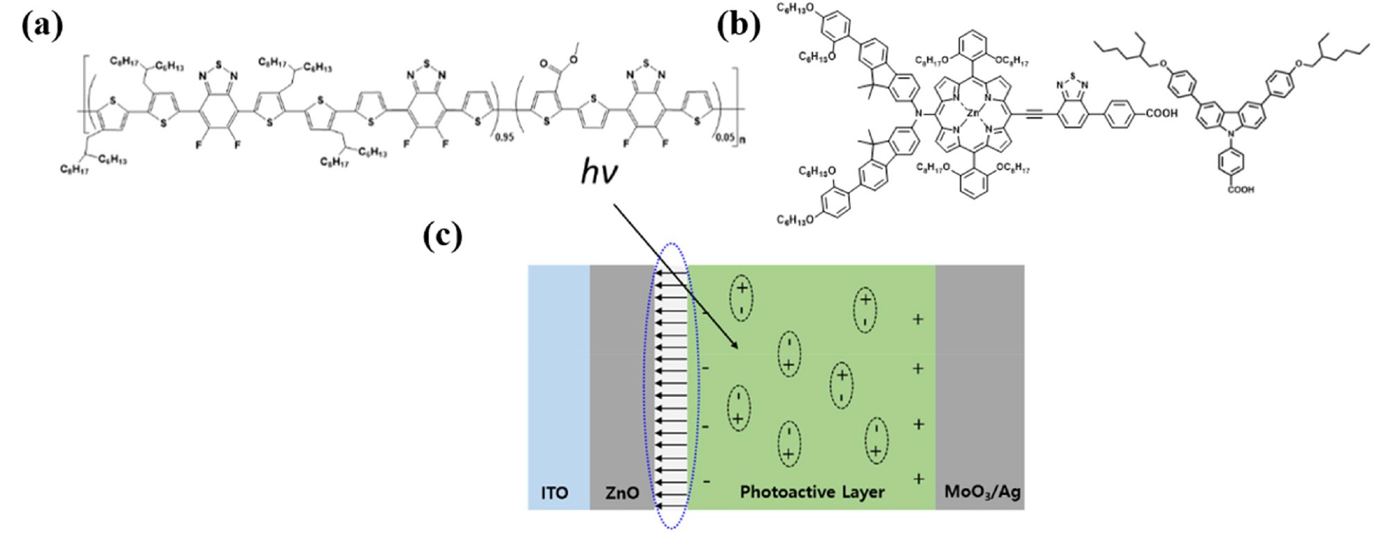
Inverted devices have been fabricated in this study with the following architecture: Glass/ITO/ZnO NPs/SMs/Photoactive Layer/MoO3/Ag. Photoactive layer and the top electrode (MoO3/Ag) is fixed in this study, while the only variable is the ETL i-e ZnO without or with SMs. Previously, our group has reported synthesis of room temperature (RT) processable high-aggregation poly(2-decyltetradecyl)thiophen-2-yl)naphtho[1,2-c:5,6-c′]bis[1,2,5]thiadiazole, 5,5′-bis-(2,2′-bithiophen-2-yl) with methyl thiophene-3-carboxylate (MTC) called as PNTz4T-5MTC polymer, via the introduction of MTC ester group in the polymer backbone25). In current study, warm-temperature processable highly crystalline difluorobenzothiadiazole (ffBT) and terthiophene (T3) based PffBT-T3 polymer has been modified with ester (MTC) to synthesize low-temperature processable PffBT-T3-5MTC polymer. Unlike warm temperature processable PffBT-T3 polymer where solution and substrate with high temperature (≥70°C) are necessary to fabricate devices, our newly synthesized PffBT-T3-5MTC polymer is nearly RT processable where substrate at RT is used while a mild solution temperature of only 40°C is enough to fabricate devices under optimized conditions. Chemical structures of the photoactive materials, SGT-021 and HC-A1 along with the device architecture is shown in Fig. 1. First of all, the absorbance of the SMs over ZnO is measured (Fig. S1, see ESI). When SGT-021 is dip-coated over ZnO and no rinsing of the film is carried out, an absorption peak around 658 nm is observed (the characteristic peak of the SGT-021 dye, the UV-visible spectra of SGT-021 and HC-A1 were shown in Fig. S2, see ESI)37). Since, we want to employ SGT-021 dye only for the surface treatment rather than a light absorbing material which is a loss to incident photons before reaching photoactive layer, the rinsing of SGT-021 SM is carried out three times with tetrahydrofuran (THF) solvent. After three subsequent rinsing, only the adsorbed SGT-021 (and HC-A1 co-adsorbent) molecules have remained onto the ZnO ETL surface.
PCEs of the PSCs are shown in Table 1. ZnO only ETL based PSCs have shown maximum PCE of 9.53% while the use SGT-021, HC-A1 and “SGT-021+HC-A1” as ETL SMs resulted PCE of 9.89%, 9.91% and 9.94% respectively (average PCEs from 15 independent devices have been shown in Table 1 and statistical PCE graphs have been shown in Fig. S3a-d, see ESI). Interestingly, short-circuit current density (JSC) as well as fill factor (FF) have been improved after employing SMs. JSC calculated from the integration of external quantum efficiencies (EQEs) lies within 4% error range, and are higher in ZnO/SMs ETL than the reference ZnO ETL containing devices (see Table 1). J-V and EQE curves are shown in Fig. 2a,b respectively. It is clear from the Fig. 2b that the EQE is higher in ZnO/SMs ETL based devices as compared to ZnO ETL based devices. The higher JSC from integration of EQE has been obtained due to the improved interface where the effective extraction of the charge carriers take place due to the induction of interfacial dipoles by SMs. When electron mobilities (µe) of the blend films using ZnO without and with SMs were measured (Fig. S4, see ESI), µe with ZnO only ETL is 4.79 × 10⁻⁴ cm2·V-1s-1 while with SGT-021, HC-A1 and “SGT-021+HC-A1” SMs are determined to be 7.83 × 10⁻⁴ cm2·V-1s-1, 1.34 × 10⁻⁴ cm2·V-1s-1 and 1.20 × 10⁻³ cm2·V-1s-1, respectively (see Table 1). Higher µes are one of the reason for effective charge extraction from the blend film giving rise to FF from SM ETL based devices.
Table 1.
PV parameters of the PffBT-T3-5MTC:PC71BM based PSCs, before and after LS
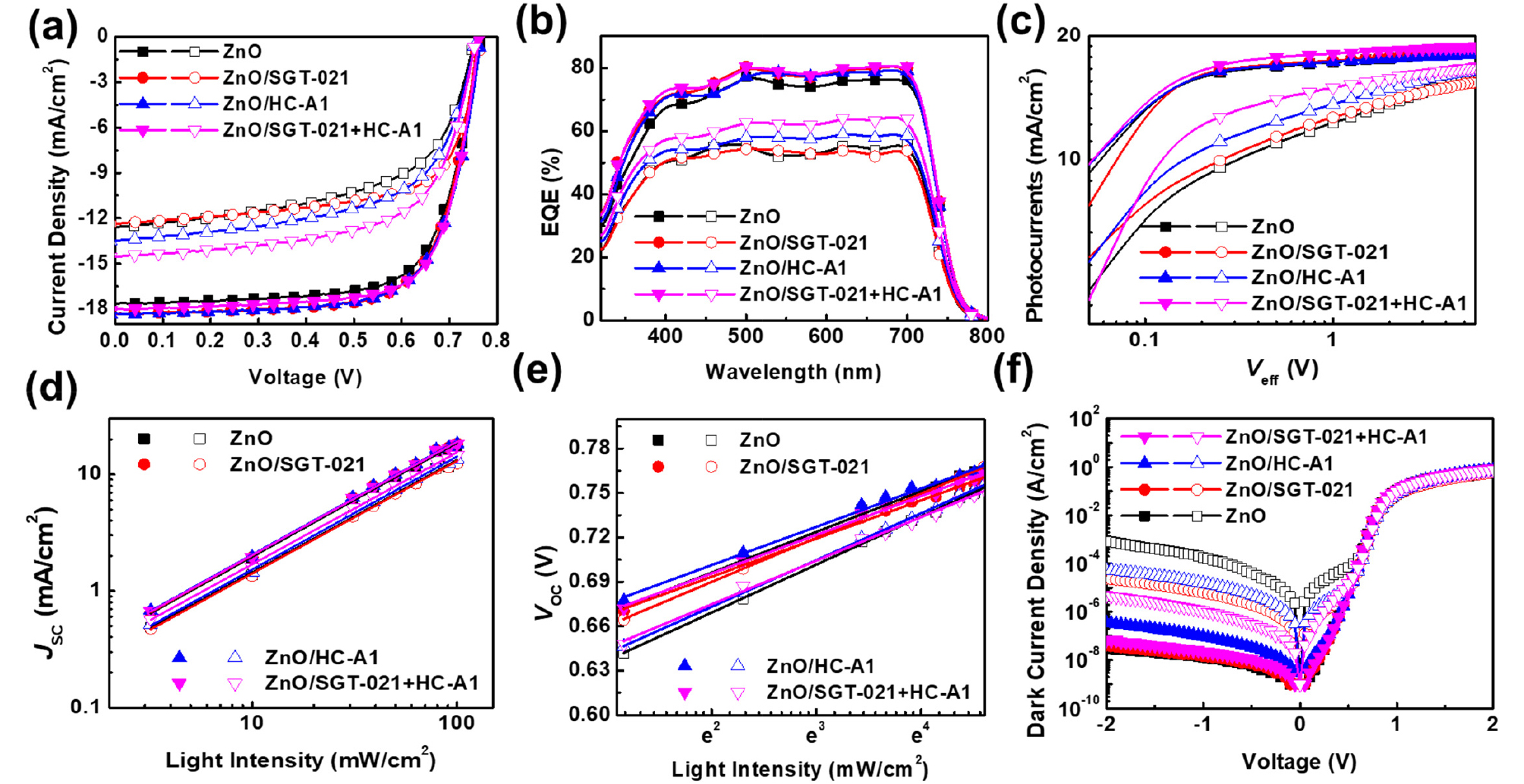
To assess the effect of ZnO/SM ETLs on charge carrier dynamics, photocurrents (see Fig. 2c) have been measured and maximum photoinduced charge carrier generation rate per unit volume (Jph,sat = qLGmax) and charge collection probabilities (Jph = qLGmaxPC) have been calculated where Jph is the photocurrent at 0V (Jph = JL - Jd; JL is the current density under light illumination and Jd is the current density in dark), Jph,sat is the saturated photocurrent at -5V, q is the elementary charge and L is the thickness of the photoactive film40). Maximum Gmax of 5.11×1027 #.m-3s-1 has been observed in ZnO/“SGT-021+HC-A1” based device, as shown in Table 2. Overall, all the devices have shown a reasonable high Gmax values in the range of 1027 #.m-3s-1 (see Table 2). Moreover, PC in PSCs having HC-A1 and SGT-021+HC-A1 as SMs is 96.71% and 95.72% (PC is 94.77% for reference ZnO ETL based PSCs), implying the effective charge collection from the PSCs which can be attributed to the high µe values of the ZnO/SMs based PSCs (Table 2). Since, the types of recombinations can be determined from the light intensity (LI) measurements at JSC and VOC conditions, a sub-linear slope of around 0.97 in all types of ZnO/SMs based solar cells (except for SGT-021 where slope of 0.9830 is observed) indicates the presence of similar amount of bimolecular recombinations (Fig. 2d, Table 2). But, a reasonable difference is observed when LI vs VOC has been plotted (Fig. 2e, Table 2) and a value of 1.069 kBT/q for ZnO and nearly a linear slope of 1.00 kBT/q has been obtained in ZnO/SM based PSCs. These results indicate that SMs have modified the interface between ZnO and photoactive layer, probably with the formation of interfacial dipoles due to the presence of terminal carboxylate (-COOH) group in the SGT-021 dye as well as HC-A1 co-adsorbent (Fig. 1c). These interfacial dipoles have efficiently extracted charge carriers from the ZnO-photoactive layer interface resulting in less number of trap-assisted recombinations (as seen from Gmax, PC and LI vs VOC values in Table 2). Before LS, almost all four types of ETL based devices have shown a very low dark currents (Jd at -2V) as shown in Fig. 2f and Table 2.
Table 2.
Characterization of the PffBT-T3-5MTC:PC71BM based PSCs, before and after LS
Light soaking testing has been carried out in a temperature controllable weathering chamber equipped with 1 Sun (metal halide based) light source and having adjustable relative humidity (RH) from 25% to 85%. These devices have been encapsulated with glass-on-glass type encapsulation using UV-crosslinkable epoxy resin and placed in the LS weathering chamber under 1 sun, 85% relative humidity while the chamber temperature has been controlled at 45°C. As shown in Fig. 4, PSCs with ZnO/“SGT-021+HC-A1” based ETL has shown the highest LS stability in the series after 1000 hrs of LS; retaining 70% of the initial PCE in best performing device. PSCs without surface modifier have shown destitute performance after 1000 hrs of LS; retaining less than 60% of the initial device PCE in the best performing device (average values from 8 individual cells have been shown in Fig. S3e-h, See ESI). In LS devices, the major contribution towards stable performance originated from JSC and FF (Table 1).
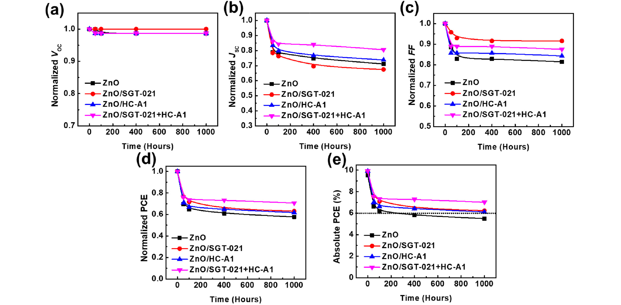
To gain the insight into device for enhanced LS stability in these devices, first of all, their EQEs have been compared (Fig. 2b). As we can see from the Fig. 2b that PSCs with HC-A1 and “SGT-021+HC-A1” as SMs have shown highest EQE owing to the efficient charge extraction from the PSCs. Gmax was highest in the case of ZnO/“SGT-021+HC-A1” based devices and reduced by only 11% from its initial value (Table 2). Interestingly, the PC after LS was highest in the ZnO/SMs based PSCs accounting to 86.74% for ZnO/“SGT-021+HC-A1”, 80.55% for ZnO/HC-A1, 79.44% for ZnO/SGT-021 and 73.95% for ZnO based PSCs. The higher PC is observed due to better and robust interface obtained with SMs. As there can be large number of photoinduced charge carries (Gmax at negative saturated voltage i-e -5V), due to improper and poor interface in the case of ZnO only ETL based devices, the charge extraction was poor and more and more charges accumulated into the device under normal operation conditions leading to reduced FF (Table 2). Furthermore, when LI vs JSC was measured, although a similar slope is observed in all the devices, but the major difference has been seen in the case of LS vs VOC where the highest slope of 1.261 kBT/q for ZnO based PSCs has been observed. In LI vs VOC measurements, lower slopes for SGT-021 dye containing ETL based PSCs imply the presence of less interfacial traps in devices, which accounts to higher FF. The effect of the presence of traps can also be observed from the dark J-V scan, where the effect of the leakage current can be observed with current density at -2V; the higher RSH, lower will be the leakage current41). It is apparent from the dark J-V scan the highest leakage current (at -2V) exist into the device containing ZnO only ETL (RSH is 1.58×10⁻⁴ Ω.cm2) while the lowest leakage current has been observed into the devices containing ZnO/“SGT-021+HC-A1” ETL (RSH is 9.09×10⁻⁵ Ω.cm2), as shown in Fig. 2f and Table 2. The presence of the undesirable parasitic leakage current in ZnO based PSCs accounted for the reduced FF via recombinations at the electrode. With the modified ZnO/photoactive layer interface with SGT-021+HC-A1 SM, the amount of the leakage current was considerably low which can be observed from the dark J-V scan (Fig. 2f) and RSH (Table 2). Therefore we deduce that ZnO surface modified with “SGT-021+HC-A1” ETL based PSCs has less interfacial traps present into the devices after LS which resulted in higher LS stability in ZnO/SM ETL based PSCs by maintaining their FF as well as JSCs (Table 2).
When the surface energies of the ETLs were measured, it has been found that the SGT-021 dye has resulted in lowest surface energy (Fig. S5, Table S2, see ESI) as compared to only ZnO based ETL. Lower surface energy is beneficial for the better interfacial contact between the photoactive layer and ETL because the organic photoactive layers itself have low surface energies. Better and rigid interfacial contact between photoactive layer and ETL is beneficial when PSCs are subjected to LS stability testing as the interface define the effective and efficient flow of charge carriers across the electrode, which in turn, effects on the photovoltaic parameters of the devices.
3. Conclusions
In conclusion, the LS stability of the PSCs have been improved with the surface modifier of an organic dye molecule. The initiation and intensification of interfacial traps between photoactive layer and the metal oxide (ZnO) ETL limits the LS stability of the PSCs. The circumvention of these traps is imperative to enhance LS stability in PSCs. Herein, the modification of the ETL surface with the help of the porphyrin based organic dye molecule (SGT-021) and co-adsorbent (HC-A1) lead to nominal enhancement in initial PCE but a huge difference is observed when these devices were placed in weathering chamber for accelerated LS stability test. In comparison to ZnO only ETL based PSCs, a 42% drop in PCE is seen with absolute PCE limiting to 5.50% while ZnO/“SGT-021+HC-A1” ETL based PSCs have shown 29% drop in PCE and an absolute PCE of over 7% has been achieved. The organic molecule coupled with co-adsorbent effectively improved the interfacial contact between photoactive layer and ETL via adsorption on the ZnO ETL and forming a rigid and stable interface. This study helps not only in the understanding of the origin of the drop in PCE under LS, but also pave a way to mitigate the sources of LS instability in PSCs leading to the fabrication of efficient and stable PSCs.
Supplementary
Materials and Synthesis
5,6-difluoro-4,7-bis(thiophen-2-yl)-2,1,3-benzothiadiazole, 5,6-difluoro-4,7-bis(3-(2-hexyldecyl)-4'-(2-hexylnonyl)-[2,2'-bithiophen]- 5-yl)benzo[c][1,2,5]thiadiazole were synthesized according to the reported literature.S1 Methyl 2,5-dibromothiophene-3-carboxylate was synthesized according to our previous work.S2 All chemicals and solvent were purchased and used without further purification, unless stated.
Monomer syntheses:
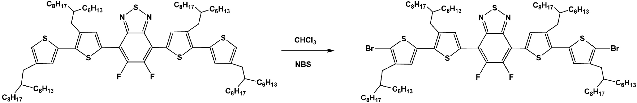
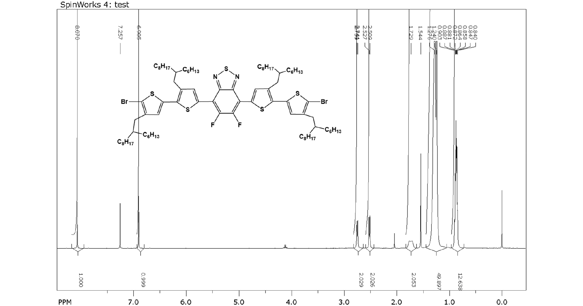
5,6-Difluoro-4,7-bis(5'-bromo-3-(2-hexyldecyl)-4'-(2-hexylnonyl)-[2,2'-bithiophen]-5-yl)-2,1,3-benzothiadiazol: 5,6-difluoro-4,7-bis(3-(2-hexyldecyl)-4'-(2-hexylnonyl)-[2,2'-bithiophen]-5-yl)benzo[c][1,2,5]thiadiazole (1.50 g, 1.07 mmol) was dissolved in 100 mL CHCl3. Then, NBS (0.39 g, 2.20 mmol) was added and the reaction was carried out in the dark for 1h. The solvent was evaporated and the crude product was purified by silica column chromatography with n-hexane as eluent to give final red liquid product (1.53 g, 92%).
1H NMR (400 MHz, CDCl3, ppm): δ 8.10 (s, 2H), 6.91 (s, 2H), 2.75 (d, J = 7.2 Hz, 4H), 2.51 (d, J = 7.2 Hz, 4H), 1.30 (m, 4H), 1.26 (m, 96 H), 0.87 (m, 24H).
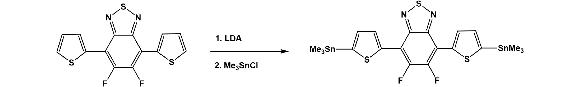
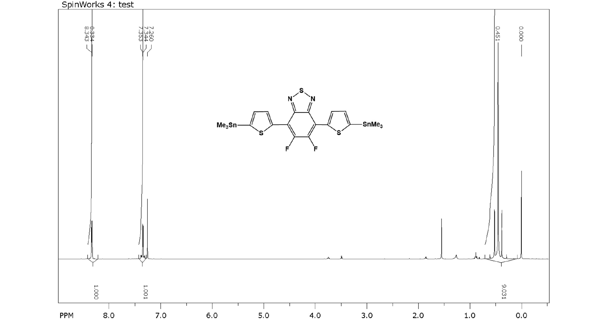
5,6-difluoro-4,7-bis(5-(trimethylstannyl)thiophen-2-yl)-2,1,3-benzothiadiazole: 5,6-difluoro-4,7-bis(thiophen-2-yl)-2,1,3-benzothiadiazole (0.51 g, 1.51 mmol) was dissolved in 100 mL of anhydrous THF in argon atmosphere which was cooled to -78°C. Lithium diisopropylamide 2M (1.9 mL, 3.80 mmol) was added dropwise to the solution and the solution was kept at -78°C for 2h. After that, trimethyltin chloride 1M (3.8 mL, 3.8 mmol) was added via syringe and the solution was warmed to room temperature and stirred overnight. Water was added to quench the reaction and reaction solution was extracted with diethyl ether to give organic layer. The solvent was evaporated and the crude product was recrystallized with methanol for three times to give the final product (0.62 g, 62%).
1H NMR (400 MHz, CDCl3, ppm): δ 8.34 (d, J = 3.6 Hz, 2H), 7.35 (d, J = 3.6 Hz, 2H), 0.45 (s, 18H).
Polymer syntheses
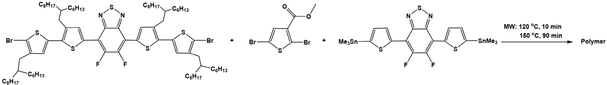
PffBT4T-T3-5MCT: 5,6-Difluoro-4,7-bis(5'-bromo-3-(2-hexyldecyl)-4'-(2-hexylnonyl)-[2,2'-bithiophen]-5-yl)-2,1,3-benzothiadiazol (295.6 mg, 0.19 mmol); Methyl 2,5-dibromothiophene-3-carboxylate (3.0 mg, 0.01 mmol); 5,6-difluoro-4,7-bis(5-(trimethylstannyl)thiophen-2-yl)-2,1,3-benzothiadiazole (132.4 mg, 0.2 mmol) were added to 5 mL reaction vial. Then, Pd2(dba)3 (3.7 mg, 4 μmol) and P(o-tol)3 (4.9 mg, 16 μmol) were charged in a glove box, followed by adding 2.5 mL anhydrous CB in argon atmosphere. The sealed vial was heated in microwave reactor at 120°C for 10 minutes following by 150°C for 90 minutes. The raw polymer was dissolved in hot chlorobenzene and precipitated in the mixture of 300 mL of methanol and 15 mL of hydrochloric acid. The mixture was stirred for 3 hours before filtration to obtain crude product which was subjected to Soxhlet extraction with methanol, dichloromethane and chloroform to remove impurities and low molecular weight polymer part. The dark green polymer (228 mg, 69%) in chlorobenzene fraction was obtained by reprecipitation in acetone followed by filtration.
GPC: Mn: 57 000 Da; PDI: 3.09
SGT-021 dye and HC-A1 co-adsorbent were synthesized by the previously reported procedures.S3, S4
Device Fabrication
All the solvents have been bought from Sigma Aldrich, unless otherwise specified. 2.0 wt% of the PffBT-T3-5MTC:PC71BM (1:1.5) in o-xylene as main processing solvent and 3 vol% DPE as processing solvent additive were prepared inside the glove box and placed at 50°C overnight. 0.04 wt% of SGT-021 dye and 0.025 wt% of HC-A1 co-adsorbent (both called as SMs) were prepared in anhydrous THF solvent and stirred at RT for 4 hours. Mixed SMs solution was prepared by physical mixing of the above prepared solutions in 1:1 ratio. Inverted device architectures have been used in this study. First of all, UVO treatment of the cleaned ITO glass (washed 3 times with DIW containing detergent, followed by three times each with acetone and IPA, and finally overnight annealing at 140°C) carried out for 15 minutes. ZnO NPs (bought from Nano Clean Tech) were spin coated over ITO at 3,000 rpm to get ~30 nm ZnO ETL. Annealing of the ZnO ETL is carried out at 150°C for 30 minutes to get compact ETL. SMs containing solutions were put into a petri dish in air and ZnO ETL containing substrates were immersed into these solutions for four hours for proper their adsorption. After 4 hours, the substrates have been rinsed in THF solvent two times for 120 seconds each, followed by 60 seconds rinsing in another THF solvent. After removal of the un-adsorbed dye and/or co-adsorbent molecules via rinsing, N2 blow was used for 5 seconds to dry the substrates. Additionally, the substrates were annealed at 100°C for 5 minutes and then transferred to the glove box for spin coating of the photoactive film. An ultrathin layer of PEIE was spin-coated over ETLs (0.2 wt% PEIE in 2-methoxy ethanol solvent). After filtration of the photoactive solution using 0.45 um PTFE filter, the solution was placed at 40°C inside the glove box for 1 hour prior to spin coating. The photoactive film was spin coated inside glove box over ZnO and ZnO/SMs ETLs at 800 rpm to get nearly 230 nm thick film. Photoactive films were for 8 hours and then transferred to thermal evaporation chamber. 10 nm of MoO3 and 100 nm of Ag were thermally evaporated over as-casted photoactive films to complete the solar cells. Devices were encapsulated via glass-on-glass type encapsulation using UV-curable epoxy resin.
For electron mobility (µe) only devices, the following device architecture has been used: Glass/ITO/ZnO NPs/(without or with SMs)/Ca/Al. Single-carrier charge mobility (µe) has been measured by using Mott-Gurney equation:
Where J is the current density, V is the voltage (V = Vappl - Vbi; Vappl is the applied voltage and Vbi is the built-in voltage), L is the thickness of the photoactive film, εo is dielectric constant of air and εr is dielectric constant of the material.
Solar Cell Characterizations
PCEs of the solar cells have been measured using Keithley 236 source under 1 sun simulated conditions. EQEs of the solar cells have been measured using K3100 spectral IPCE measurement system. Light soaking has been carried out in 1 sun calibrated Keithley 3600 solar cell reliability system, equipped with heat and humidity. DSA100 Drop Shape Analyzer is used to measure contact angles and then Owen-Wendt’s Method is used to calculate surface energies of the ETLs.
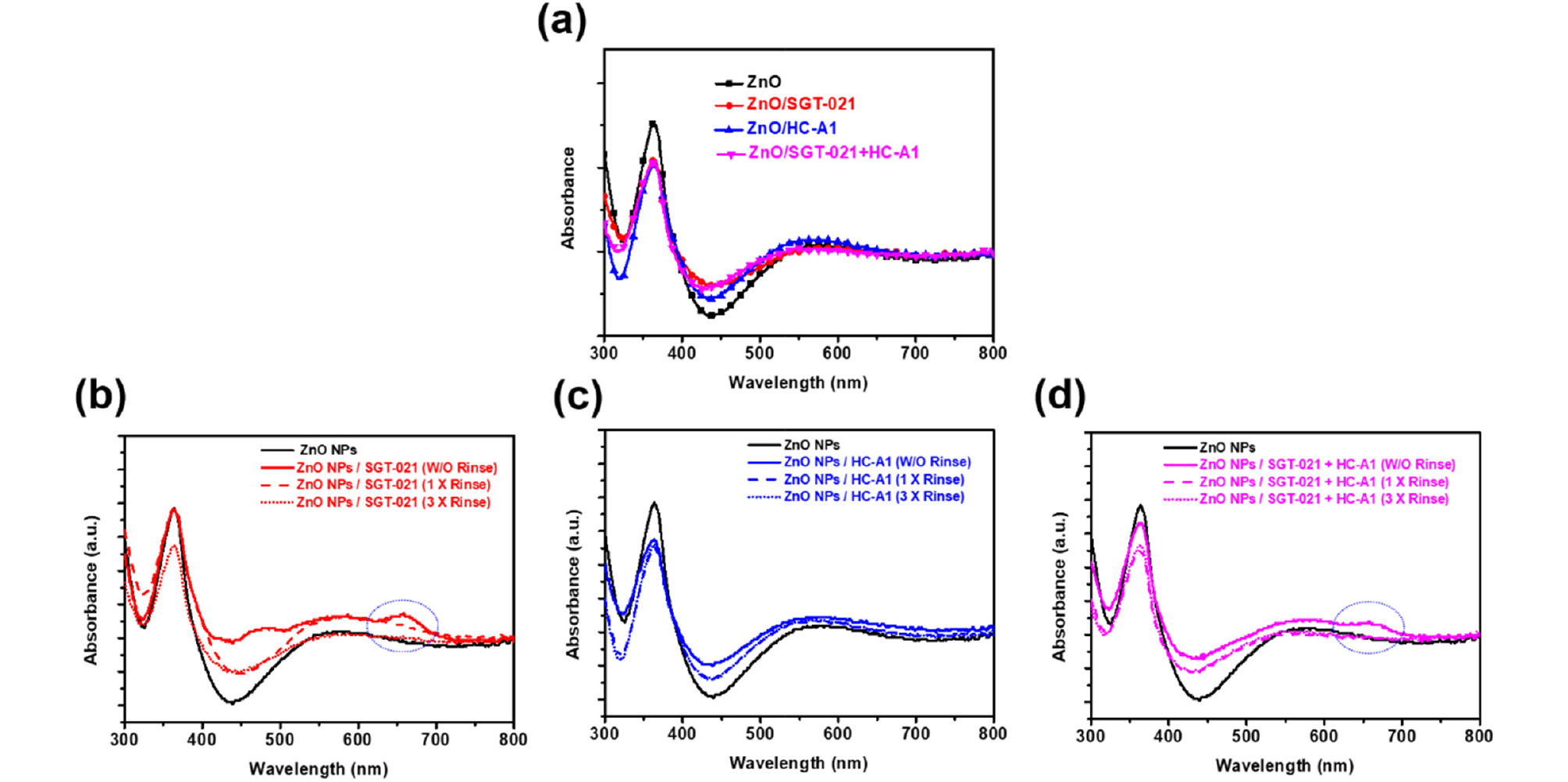
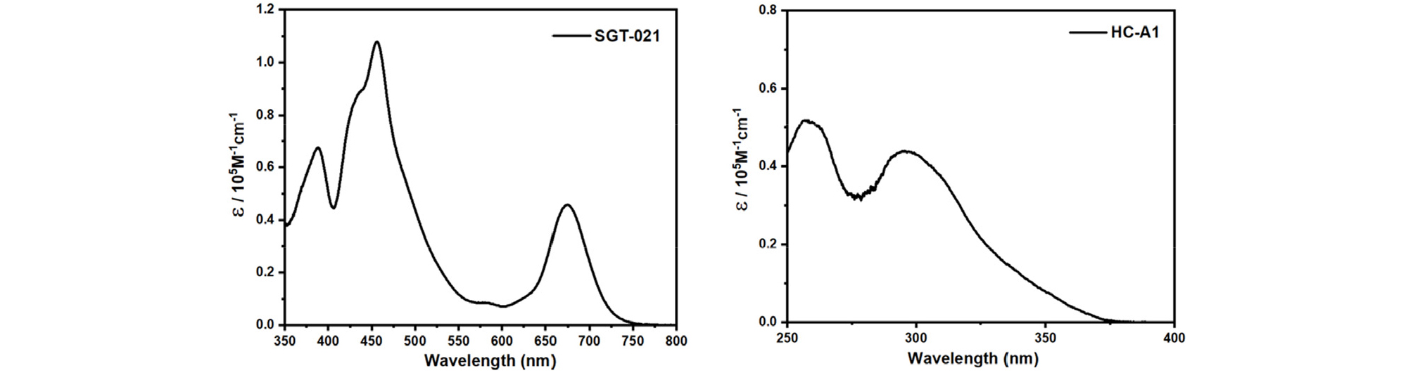
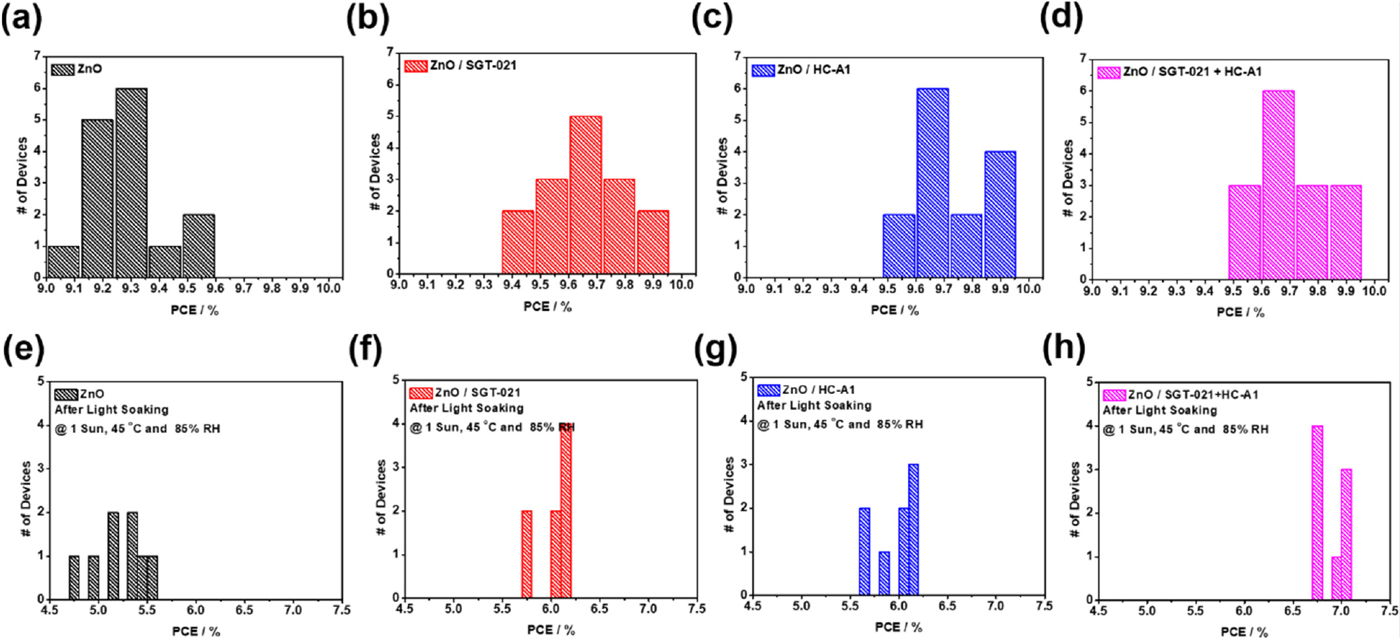
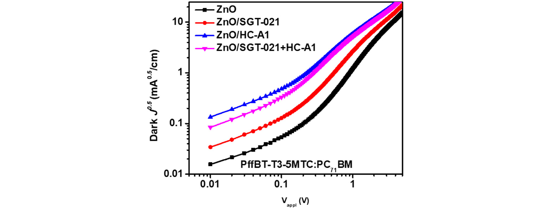
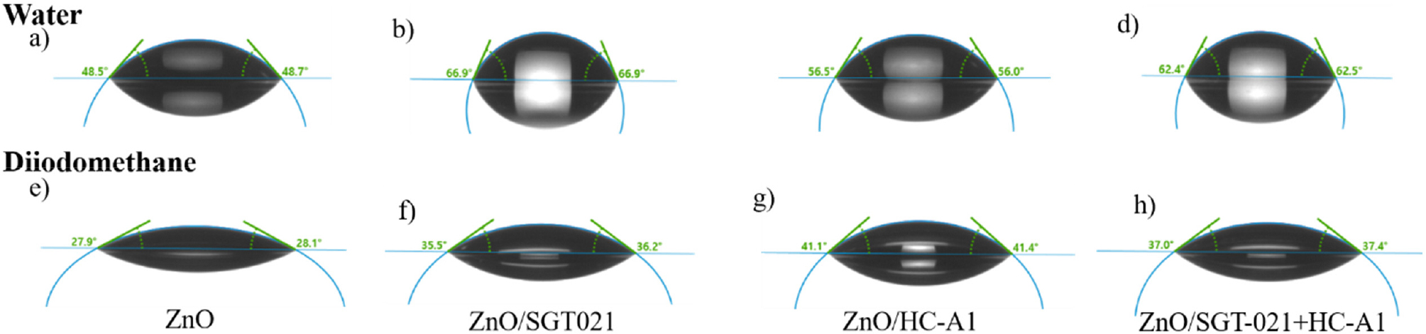
Table S1.
PV parameters of the LS PffBT-T3-5MTC:PC71BM based PSCs
Table S2.
Contact angles and surface energies of the ETLs and photoactive layer (PffBT-T3-5MTC : PC71BM) over ETLs
| Film | Deionized Water [θ] | Diiodomethane [θ] | Surface Energy [mN/m] |
| ZnO NPs | 48.60 | 28.00 | 57.08 |
| ZnO NPs/SGT-021 | 66.90 | 35.85 | 46.27 |
| ZnO NPs/HC-A1 | 56.25 | 41.25 | 49.78 |
| ZnO NPs/SGT-021+HC-A1 | 62.45 | 37.20 | 47.77 |
References
S1. H. Hu, K. Jiang, G. Yang, J. Liu, Z. Li, H. Lin, Y. Liu, J. Zhao, J. Zhang, F. Huang, Y. Qu, W. Ma and H. Yan, J. Am. Chem. Soc., 2015, 137, 14149.
S2. S. Rasool, D. V. Vu, C. E. Song, H. K. Lee, S. K. Lee, J.-C. Lee, S. J. Moon and W. S. W. S. Shin, Adv. Energy Mater., 2019, 1900168.
S3. S. H. Kang, M. J. Jeong, Y. K. Eom, I. T. Choi, S. M. Kwon, Y. Yoo, J. Kim, J. Kwon, J. H. Park and H. K. Kim, Adv. Energy Mater., 2017, 7, 1602117.
S4. I. T. Choi , M. J. Ju , S. H. Kang , M. S. Kang , B. S. You , J. Y. Hong , Y. K. Eom , S. H. Song and H. K. Kim, J. Mater. Chem. A, 2013, 1, 9114.
