

Nomenclature
Subscript
1. Introduction
2. PV Module Accelerate Stress Test Types
2.1 Thermal cycling test
2.2 Humidity freezing and Damp Heat tests
2.3 Ultraviolet (UV) light exposure
2.4 Static and dynamic mechanical loads
2.5 Reverse bias hot spot test and Bypass diode thermal test
2.6 Hail test
3. PV Module Accelerated Testing Levels and Prioritization
4. Conclusions
Nomenclature
Isc : short circuit current
Rsh : shunt resistance
Pmax : maximum power
Voc : open circuit voltage
Subscript
PV : photovoltaic
AT : accelerated testing
UV : ultraviolet
TC : thermal cycling
IEC : international electro-technical commission
DH : damping heat
HF : humidity freezing
RH : relative humidity
EVA : ethyl vinyl acetate
DML : dynamic mechanical load
PCT : pressure cooker test
TPT : tedlar polyester tedlar
PET : ploy ethylene terephthalate
PO : poly olefin
HAST : high accelerated stress test
c-Si : crystalline silicon
SML : static mechanical load
DML : dynamic mechanical load
1. Introduction
The PV module elements, including cells and polymeric materials, must be confined from the catastrophic failures (hard/reliability failures) and degradation losses (soft/durability losses). These are caused by stresses together with humidity, ultraviolet (UV) radiation, temperature, wind, hail, and high system voltage, as well as effects including broken interconnects, hotspots, corrosion, encapsulant discoloration and delamination1, 2).
The reliability and durability are two important factors for the performance of the PV module to work for 25-30 years under the operating conditions encountered3). A PV module fails to supply the service if its power output decreases more than 30% before 30 years, i.e. 1%/yr in its using environment4). If any of the PV module components are replaced (or removed) from the field environment before its warranty period because of any type of failure, and power drop, then those types of failures are called hard failures. The degradation losses are those when the performance of the PV module degrades but still meets the warranty requirements5). The mechanisms of failures and degradation in the PV module are mainly related to the construction/packaging/design and the operating environment.
There is a dramatic change in the PV module design and construction since 1975, and the change includes from cell type (mono-Si to ploy-Si and mono-Si with various thin-film technologies), the substrate (from fiberglass board to polymeric backsheet), encapsulants (from silicone to ethylene-vinyl acetate [EVA]), superstrate (from silicone to glass), interconnect between cells (from one to multiple), cell string (from one to multiple) and bypass diode (from none to multiple)6).
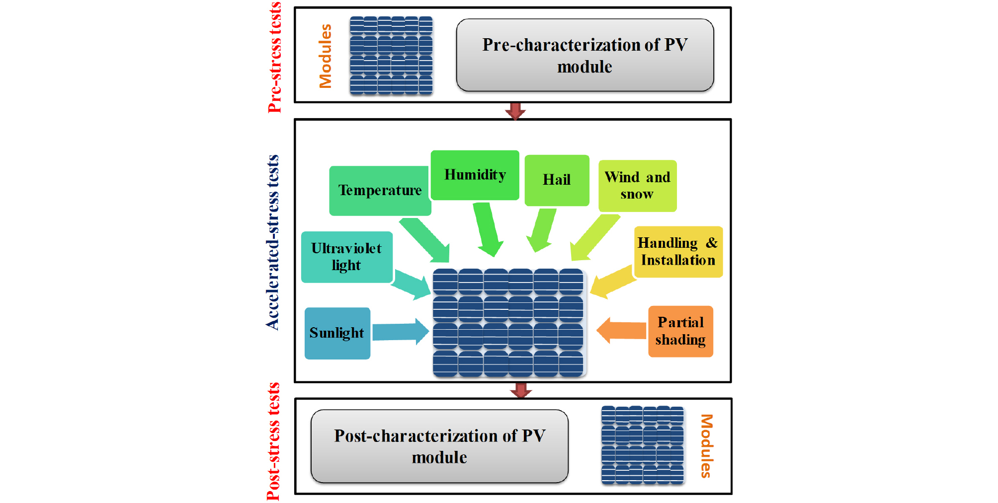
To evaluate any PV module cell/system, one needs to analyze the field data that are collected in the entire lifetime of the PV module. However, it is difficult for the manufacturer and stockholders to wait and see failure and degradation losses before putting new PV cell into the outdoor environment. Hence a predictive model for the lifetime expectancy and the performance of the new photovoltaic cells and panel is extremely significant for the producers as well as for the customers. For the photovoltaic cells and panel, the accelerated aging test is one of the major analyses, for the base of the predictive model7). The basic concept involves several accelerated stress tests through pre- and post- characterization techniques. In the accelerated testing (AT) programs, the PV modules undergo different kinds of stress tests at higher levels than the field/use stress levels besides pre- and post-characterization of materials and modules from durability, reliability and safety perspectives. Figure 1 shows the conceptual representation of AT program on the modules.
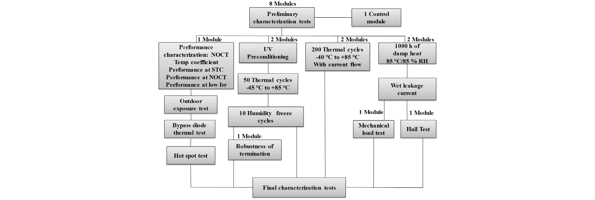
The developed PV modules should undergo the standard qualification test programs that are established by IEC standards (IEC 61215 for c-Si, IEC 61646 for thin film, and IEC 62108 for concentrated photovoltaics) and has to be developed for the comparative and lifetime test programs. For understanding of the testing sequence, IEC 61215 qualification standard is shown in Fig. 28). In this review, we will briefly discuss about different types accelerated stress tests, level and prioritization to expand the life expectancy for the PV module by means of the standard test protocols (IEC 61215-1, IEC 61215-2, IEC 62108).
2. PV Module Accelerate Stress Test Types
A reliability test can be accelerated in multiple ways by increasing the level of the experimental variable like UV light, humidity, temperature, or voltage. These tests lead to certain failure mechanisms in chemical processes such as degradation of chemical in adhesive bonds or polymeric matrix additives. One need to choose the parameter(s) that must be measured for better monitoring of the failure modes. These parameters help to evaluate and describe the constitutes of a failure corresponding to the parameters chosen and the accelerated tests that are used to induce various kinds of failure modes in PV modules9). There are few methods to understand the accelerated aging test for photovoltaic cells and panels indoor by mimicking the real filed conditions. The following sections will briefly discuss these accelerate test methods.
2.1 Thermal cycling test
The thermal cycling (TC) is extensively used profile to know the evolution of degradation. This allow us the analysis of the PV module’s reliability of manufacturing, construction processes, and estimated field performance. The thermal cycling method uses the variation of the temperature between -40°C and 85°C and the injected current to imitate constant illumination. The quantity of the cycle varies as a function of the upper limit of the temperature, 500 for 110°C, 1000 for 85°C, or 2000 for 65°C and the injected current in the solar cell is calculated as 1.25×Isc×no. of suns, where Isc represents the short circuit current10). Although many reports are presented on the degradation of PV module caused by temperature and corrosion in the literature11-13), the study still needs more attention and further work to understand and explain these aging factors.
A recent study by Khan et al.14) explains the failure and degradation behavior of the c-Si PV module set over a concrete slab performed via a TC stress test. The connection between the TC duration and device is established. In this study, the authors have used monocrystalline PV modules with an area of 1540 cm2 and the rigid module (fixed on concrete slab) consists of 36 cells, with an Al frame (cell area =31.2 cm2). The ability of the module was evaluated towards withstand fatigue, thermal mismatch, and other stresses caused by temperature fluctuations for 200 thermal cycles in a NEC EC-1100 chamber (M/s. NET Co. Ltd., Suwon, Korea).
Figure 3 depicts the measurement of the I-V characteristic for both the PV modules before and after thermal cycling (100 and 200) and a clear sign of increasing in the series resistance. This is mainly related to the thermal exhaustion undergone by the PV module. The corresponding P-V characteristics are given in Figure 4.

Fig. 3
I-V curves after 0, 100, 200 thermal cycles for PV module (a) without concrete and (b) with concrete. The difference in the Isc values are shown in the inset14)

Fig. 4
P-V curves after 0, 100, 200 thermal cycles for PV module (a) without concrete, and (b) with concrete13)
After 200 thermal cycles, the observed power loss is approximately 3% and 2% for the reference and concrete PV module respectively. There is an increment in the I0 value, about 3.1 and 2.9 times from its initial value of the reference and concrete PV module respectively. In this study, the reduction of Rsh (shunt resistance) was also observed after thermal cycles treatment approximately by 91% and 71% of reference and concrete based PV modules respectively. It shows that there is a slight decrease in the performance degradation in the concrete PV module via protecting the backside of the PV module and also the concrete slab helps from thermal soaks.
2.2 Humidity freezing and Damp Heat tests
The reliability and long-term durability of the PV module are associated with the durability of encapsulant and its interface with glass and back sheet15, 16). Humidity has the potential for the degradation of many electronic products along with the PV module. Corrosion and loss of adhesion between layers cause due to the penetration of moisture into the electronic package. In the damp heat test, acceleration of moisture ingress and see the reaction along with the increase in the temperature and high humidity. According to the IEC-61215 standard, 1000 h damp heat (DH), 10 cycles of humidity freezing (HF), and 200 cycles of TC are the common specifications used to screen the PV modules in the industry17, 18).
Dadaniya et. al. has exposed the PV module in a dose based model to understand the degradation in encapsulant-glass adhesion strength with HF and DH conditions along with temperature variation. Fig. 5a shows the rate of degradation and was least under exposure to 55-100% RH and highest in 70-100% RH. In this study, the authors have equated the peel strength to the adhesion strength as reported in the literature and ignored the plastic and viscoelastic deformations that arises in a few backsheet and encapsulant materials20, 21). Fig. 5b shows the variation of the degraded adhesion strength with exposure time. The DH exposure has maximum loss in adhesion and is highest at 57%, followed by 16% for the HF exposure and least 1.4% for TC exposure. The HF and TC are less degraded because of its limited exposure time (240 h) and relatively low humidity and temperature exposure respectively19).

Fig. 5
(a) Predicted water vapor pressure at the center of the EVA-glass interface inside the aged PV module under different exposure environments, and (b) variation of the degraded adhesion strength with exposure time18)
2.3 Ultraviolet (UV) light exposure
Another important variable on the accelerate stress test for the PV module is UV light exposure, because it degrades some of the polymers and adhesives. During accelerate UV test; keep in mind that selection of high temperature can always accelerate the UV-induced damage. And need to observe whether the reciprocal relationship exists between the exposure duration and intensity of light. In recent studies, floating PV systems are more attractive as of its cost effectiveness and PV systems operate in an environment with higher humidity because of reservoirs and ponds22). As higher UV light reflected from the surface water, it is an important stress factor to consider and a different acceleration test required to improve the durability according to the variety of field conditions23).
During the UV exposure test the exposure levels should be kept at similar levels to experience the field result close to the actual outdoor exposures. The time lapse between the actual field and accelerate test field of UV exposure differs because of four to six equivalent sun hours per day. The constant exposure may give the acceleration factor of four to six times. To simulate the same degradation mechanisms a long-term UV exposure requires a very elongated test times. For an effective way of reproducing the degradation mechanism some studies propose the technique of combining the different accelerated test variables in a single test or sequential testing24).
Li et al. (Fig. 6) showed the result of combining the DH tests or pressure cooker test (PCT, 121°C/100% RH, 100 h) with UV tests on three different commercial backsheets includes TPT (Tedlar Polyester Tedlar), PET, and PO. These backsheets consist of three different polymers namely polyvinyl fluoride, poly ethylene terephthalate (PET), and ployolefin (PO). The accelerated aging test resulted in changing the appearance, yellowing index and peeling strength25). For the quick evaluation of durability of PV encapsulant and saving the sequential testing time, high accelerated stress tests (HASTs) or pressure cooker test also been used. For further investigation of degradation mechanism the test can be extended with higher relative humidity (100%), temperature (105-130°C) and water vapor pressure26). The peeling strength between backsheet and glass in mini modules during these tests are given in Fig. 6a. The results show a higher peeling strength for PET. The Damp heat and PCT may decreases the peeling strength by half in this study, but further tests to be done for more analysis. Fig. 6b shows the change in the yellow index of the three backsheets in different stress tests. The yellowing is more in shorter time for the materials TPT and PET with the sequential test PCT 100 h/UV as compared with sequential test DH 1,000 h/UV.

Fig. 6
(a) Peeling strength between the backsheet and glass for mini modules after different sequential tests, and (b) change in yellowing index (ΔYI) of mini-modules in different sequential tests25)
2.4 Static and dynamic mechanical loads
The Mechanical load test is a standard qualification test protocol for the PV module product. The test is performed by simulating the combined wind and snow as a static load. The outdoor field operating conditions & handling and transportation conditions are not necessarily static. One needs to understand the effect of both static and dynamic load test and need to analyze their interaction with climatic conditions. Each new type of module has to undergo a series of stress test such as climatic, electrical and mechanical, which are well established and accepted standard protocols IEC 61215 and IEC 6173027, 28). Before installation, the module experiences mechanical stress during the transportation in terms of vibrations and shocks29). After installation, the module exposed to static stress by means of snow and dynamic stress with wind as loads30). The reliability of the module with respect to wind and snow loads can be observed in the static mechanical loading test (SML) standards. The test consists of static load of 2,400 Pa with three 2 h cycles to the back and then to the front. For the heavy load test, a load of 5,400 Pa applied to the front side at the end of the last cycle. The American standard IEEE 1262 proposed an additional test as dynamic mechanical load (DML)31) test with 10,000 cycle at 1,440 Pa at least 3 sec/cycle. BP Solar reported that there was strong power loss after combining the dynamic load test with the climatic stress at modules with cracks, but not in the static load test32).
Simon et. al. studied on both static mechanical load (SML) and dynamic mechanical load (DML), and 672 h of damp heat (DH) treatment over 15 full-size single crystalline silicon PV modules33). The fracture mechanism of silicon showed the propagation of micro cracks and/or cell breakage depending on the maximum bending radius of the module and not on the number of the module. Table 1 shows the power loss of the module before and after for both the mechanical loads (static and dynamic). The power losses are a bit higher in static load modules when compared with the surviving dynamic load modules. The surviving modules are those, which show there was no increase of number broken cells among all the modules.
Table 1.
Module power losses after dynamic mechanical load (DML) and static mechanical load (SML)33)
Dynamic load test has better sense for contact problems from the bad soldering than the static load test. If the number of cycles in dynamic load increases, it leads to the weakening of the solder joints and or copper ribbons themselves. During the damp heat test over eight modules were exposed to 672 h 85°C/85% RH, four modules with and four modules without pre-treatment by static and dynamic mechanical loads were observed. There was no noticeable corrosion effect in the damp heat with dynamic load and a power loss of 2.3% and 1.7% for the modules with and without mechanical pre- treatment was observed respectively as presented in Table 2.
Table 2.
The average change of changes of electrical parameters for 15 single crystalline modules after mechanical load test with subsequent damp heat of 672 h, the same damp heat exposure only, and data from PI Berlin after 1,000 h of IEC damp heat treatment (also for single crystalline modules)33)
|
ML& Damp heat (672 h) |
Damp heat only (672 h) |
Damp heat only PI's IEC data (672 h) | |
| ΔPmax | 2.3% | 1.7% | 1.1% |
| ΔIsc | 0.6% | 0.1% | 0.7% |
| ΔVoc | 0.5% | 0.3% | 0.5% |
| ΔFF | 0.9% | 1.2% | -0.04% |
With the static mechanical load, micro cracks and broken cells can be detected efficiently with electroluminescence because of higher pressure in the standard SML. While dynamic mechanical load tests effects on the mechanical robustness of the solder contacts in PV modules.
2.5 Reverse bias hot spot test and Bypass diode thermal test
Another important aspect affecting the reliability of the PV power generators are the hot spot failures. The hot spot failure of the PV module is mainly due to the power mismatch in some cells among the PV module and operates in reverse as a load by the power generating unit. It consumes energy and generates a lot of heat, which may cause the fire in serious cases and lead to the safety issue in the large scale PV power stations34-36). It is important to study and analyze the hot spot failures in detail before it affects the entire system. There are several studies available for treating the hot spot faults, the general one is infrared (IR) thermal imaging. The IR thermal imaging is able to find out the hot spot module and the distribution of the hot spot by showing the color difference in the heat-generating cell and standard cell in infrared camera37). This process is quite expensive and high precession required and autonomy is poor. Along with the IR method, another technique is finding the electrical characteristics of the module where the hot spot occurs38, 39).
In diagnosing the hot spot cell, one must shade a cell in a module and observe the rate of current change in a particular voltage range of the I-V curve40). This study is valid only for those cells which have large reverse leakage current and the process of diagnosis is weightier. Another method of diagnosing the hot spot module is by injecting the AC signal into the PV module and analyzing the difference in the impedance spectrum41). A recent study by Ma et. al. shows the diagnosing of hot spot faults by the I-V curve of the PV module with a distance calculation between the scan point and the lines produced by the points42). Through this method, various types of I-V curves can be quickly renowned to diagnose hot spot faults and the effect of this method was evaluated with PV power station field data.
To decrease the reverse bias voltage on shadowed or current limiting cells, bypass diodes can be utilized to turn on automatically in the presence of any current mismatches43). The recurring hot spot event may lead to accelerated aging and thus increases the probability of the fault44). Though the bypass diode cannot avoid the hot spot occurrence but can limit the power dissipation45). They have a basic feature that is fully suited for the normal operation of the PV module, as they activate themselves automatically only when needed. In case of any mismatch, the bypass diode turns ON because of the control algorithms (the maximum power point tracking). This algorithm can lower the current delivered by the PV system by putting the diode in the ON position and made the system work in a safe region46). As a result, the strategy is having some success in limiting the hot spot.
2.6 Hail test
Thus, the approach is encountering some success in limiting the hot spot. The effect of hail on the PV module is another main reason why the PV module loses its reliability. Analytical and experimental studies should be performed to estimate the impact of hail on PV modules. Generally, two types of PV modules are used:47) (1) rigid plate with a glass layer on the outside to protect the module from the mechanical loads; (2) semi-flexible plates with a protective polymer must be fixed to flat or curved surfaces. The PV modules operate in outdoor conditions such as thermo-hygrometric cycles; snow, wind, and hail are the main source of damage and degradation before its lifetime. The hail test was carried out using pneumatic equipment observed the current losses from the I-V and clear visual pictures of micro-cracks from the electroluminescence and their effect on the electrical response48, 49). IEC 61215 needs to meet by all newly manufactured PV modules in Europe regardless of type and materials22). The IEC 61215 performs hail impact simulation tests by firing a formed ice ball on to the PV module with pneumatic actuators and the parameters for the test as 25 mm ice ball diameter and an impact velocity of 23 m/s50).
On the other hand, repeatability of the tests is important during the test process. Kilikeviciene et al. studied the hail simulation testbed aimed at identifying the required conditions for hail simulation and analyzing the performance parameters before and after the dynamic impact of the PV modules. The conducted tests revealed that the PV modules suffered from harsh damages, micro-cracks in the crystalline structure when exposed to the force, and generated power losses of 2.33% to 4.83%. With increasing the force impacting on the module led to the increase in the power loss to 8.29%51).
3. PV Module Accelerated Testing Levels and Prioritization
In the above sections, we discussed the selection and duration of accelerated tests applicable to the PV modules that have been acknowledged. In this, we will discuss how to prioritize these accelerated tests. The prioritization is based on the perspectives of both reliability (failure) and durability (degradation). There is a great need to keep a database based on the technology, climate-specific, and wear-out failures in the old field that is similar/identical to the current generation construction characteristics of the modules. Based on the wear-out failure database, several accelerated tests need to be done for identifying climate-specific conditions on the number of commercially available modules. Whereas the prioritization of the accelerated tests for reaching the qualification testing requirements may follow the qualification test failure database of different laboratories. The objective of qualification testing is to identify the major preliminary failure modes in the field with no attempts to create a product life under normally used conditions. The current qualification testing program (IEC 61215 and IEC 61730) based on the initial field failure database from different test laboratories can help in prioritizing the accelerated stress test, which could allow the manufactures to successfully pass the qualification test and launch the product in the market place.
Top three accelerated tests for c-Si modules sensitive to meet the qualification testing standard of IEC 61215 (based on the testing of 1,111 modules of the most recent 2009-2011 designs) humidity freeze, thermal cycling, and DH52). After completion of each accelerated test, a visual inspection test, wet resistance failure criteria and insulation test for the identification of failures has to be done. The power degradation limit of 5% for the c-Si after the accelerate test from the initial value is accepted. Different PV module manufacturing companies has shown less than 20% power degradation over a lifespan of 25 years as a warranty limit. Table 3 gives the power guarantee percentages of the PV modules fabricated by various companies. The best performance was given by Sun Power company fabricated PV module with only 6% power degradation in 25 years of lifetime. The lifetime testing, the power degradation limit may be determined based on the warranty limit.
4. Conclusions
Disquiets about PV modules’ performance drifting (durability) or becoming outdated early (reliability) are major obstacles to PV deployment and project financing. Accelerated testing is a way to evaluate the reliability and durability of PV modules by persuading failures and degradation in a short period of time. The accelerated tests use more severe operating conditions than the original field conditions to replicate the actual field failure mechanisms. The current review gives the detail observations of the present and future state of PV module accelerating tests. Based on the literature, there is much need to improve the accelerating test protocols for relative and lifetime testing of PV modules. The accelerating test conditions emphasize on the selection of particular test corresponding to a specific failure mode and analyzing the PV module stature and technical failures after applying the test. The studies on accelerating tests till date have suggested and successfully mitigated several kinds of failure and degradation modes that occur in PV modules in real time working conditions. The failure and degradation modes of PV module are mainly dictated by the construction and the real field working conditions in which they operate. Although, the accelerated tests are successful to some extent, still there is much need of making a vast database especially on climate conditions by comparing the old PV plants (10-30 years) that have identical characteristics to the present generation modules. This will help us to develop different accelerating tests that are prioritized according to specific climate conditions.
